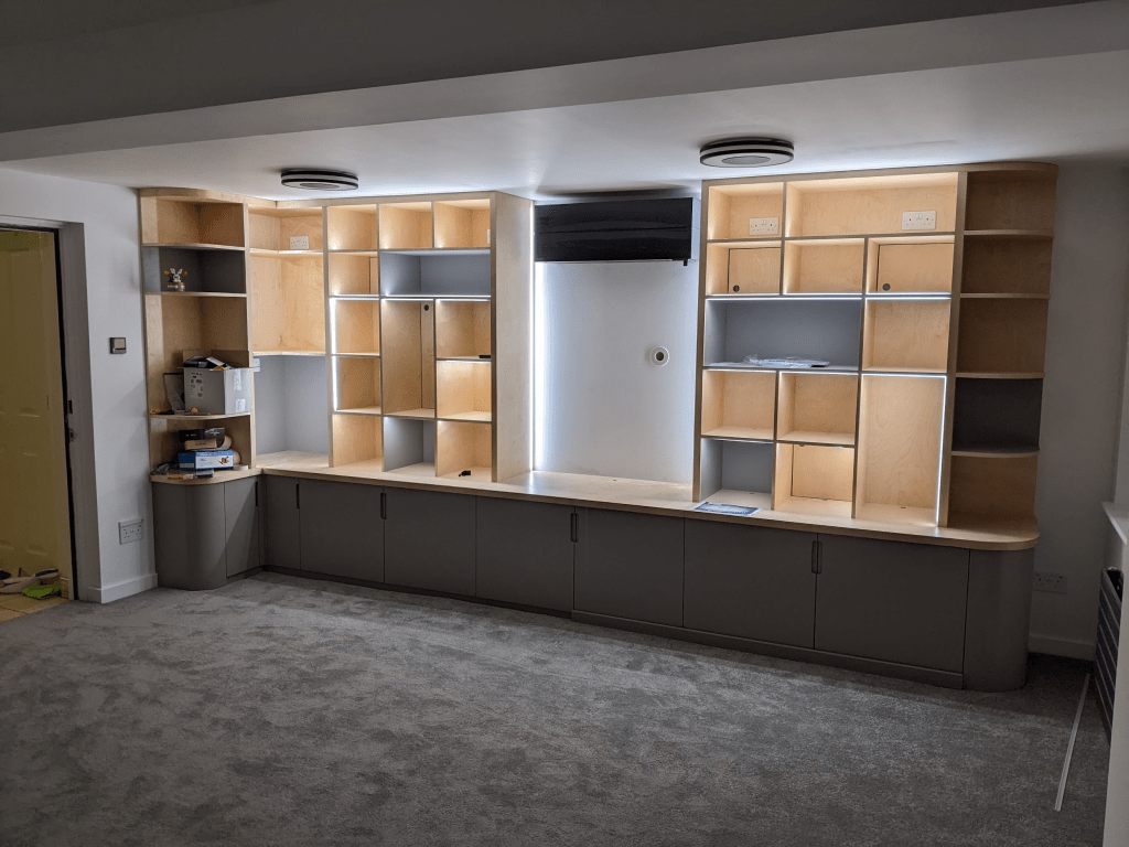
Continuing from part 1 where I talked about the “what” of how I built a mini Blackpool Illuminations for our new board game storage unit, this is the “how”. A lot more technical than the last, you can just scroll through for the pictures and this video.
After about three seconds of research, I was hooked onto using WLED to control the LEDs. It ticks a lot of boxes – a web interface & mobile app, Home Assistant integration, it runs on cheap ESP32 microcontrollers (tiny CPUs with WiFi and bluetooth that are popular for IoT products), and is easy to mod (C++, baby!)
I have some ESP32s hanging around, and it would be possible for me to assemble a control board from them + some other bits, but QuinLED has done a load of hard work on this already with his Dig series of ESP32 digital LED controllers that come with WLED pre-installed. These ensure you’ve got stable power, fuses, data line resistors etc – I could’ve done something like this with enough time, but I’m sure I’d miss an important piece. The pricing of QuinLED’s stuff is very reasonable, and comes with some nice bells & whistles. I picked up a QuinLED DigOcta controller as it supports eight LED data outputs (I needed six; one for each strip), and the power boards for it had enough fused connections for all of the power injectors I’d need. I also grabbed some other QuinLED bits to save on shipping for future projects.
Control Box
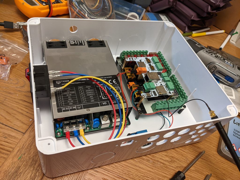
To safely contain the control & power stuff and keep it away from curious fingers, I assembled it into a junction box – a plastic enclosure – with a suitable power supply, the QuinLED DigOcta controller stack, 6x 3-pin outputs for the LED strips, 10x 2-pin outputs for power injectors, an ethernet port, an external WiFi antenna, 1x USB-C, an A/C switch, a power-saving relay and a microSD card reader. Finding a box the right size was surprisingly tricky as the power supply is quite large – I spent a long time scrolling through Amazon, eBay, and AliExpress looking for something with enough space to squeeze everything in.
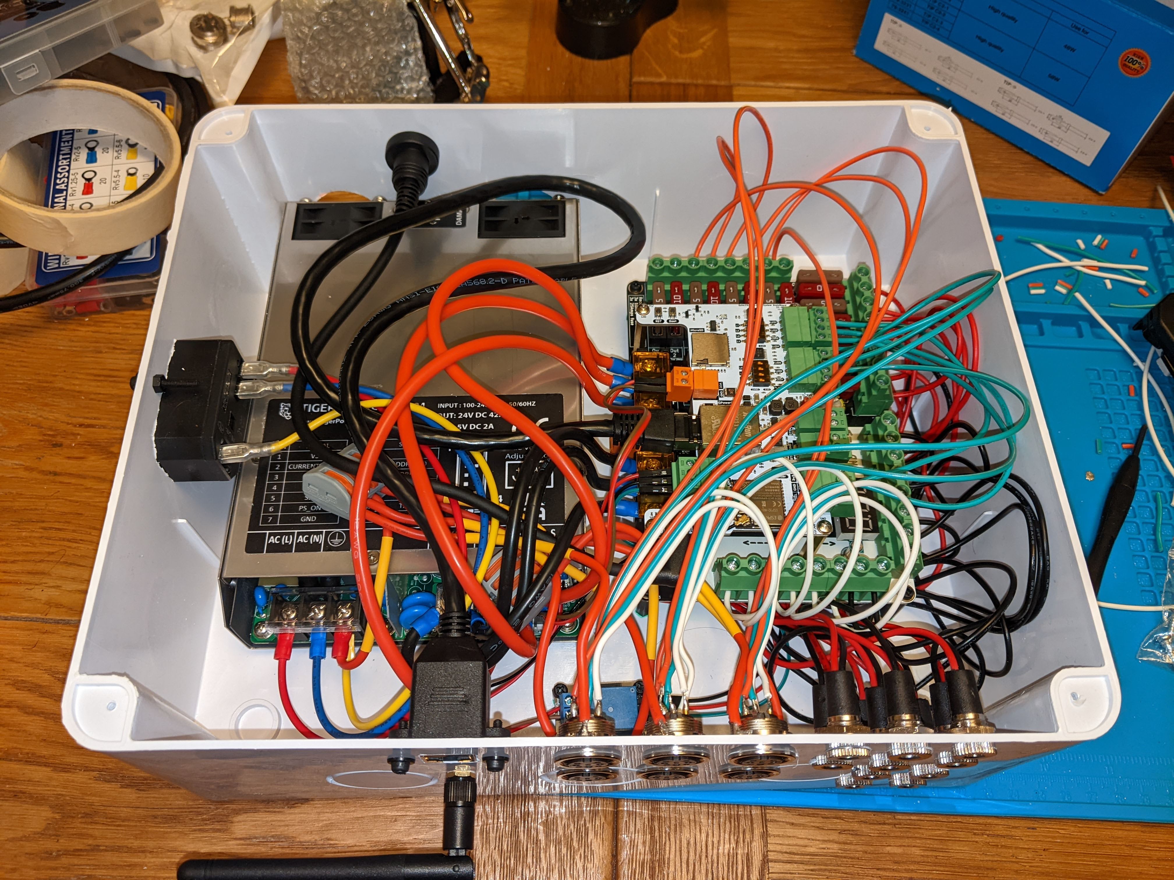
Breaking down a few things there:
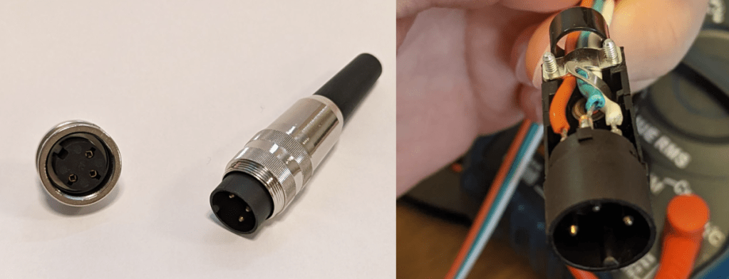
- 3-pin outputs – power+data – each LED strip requires a positive voltage, a negative voltage (or ground) and a data input. To join strips together (whether directly or with a wire in between), you just need to connect the 3 pins from one strip to another. A relative recommended a family of audio-style DIN jacks for this that have a solid feel and screw into their sockets.
- 2-pin outputs – power only – long runs of LEDs need extra power adding in the middle “power injection” and the end. I used simple DC barrel jacks like you see on loads of small electronics at home.
- Power-saving relay – when addressable LEDs are “off” aka zero brightness, they still suck a bit of power. In this situation, I use a relay to sever the positive voltage to the strips, turning them actually off.
- External WiFi antenna – ESP32s have the option of either an antenna that’s built-into the chip, or adding an external antenna that is bigger and can be positioned further away from the electrically-noisy innards. I don’t actually use this now, but it was handy during construction as I was far away from a network port.
- USB-C – This allows me to power the QuinLED controller for safe testing (without getting 240v AC involved), and for flashing new firmware on should the ethernet/WiFi on it become unusable for some reason.
- microSD reader – this was an opportunistic addition – I was vaguely thinking about rendering more complex lighting effects offline as a kind-of video stream, storing on a microSD card and simply using WLED to play them back. Thanks go to a friend who quickly 3D-printed a panel mount adapter for it while my own printer was out of action (in a cupboard escaping the builders’ dust).
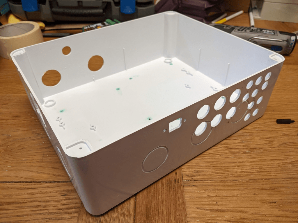
Making holes and ports in the box was a surprisingly messy task – armed with a drill, some new step-drill bits, a Dremel and the vacuum, I bored/ground/milled/drill-stabbed many holes for all of the sockets, ports, the switch and importantly – some ventilation holes for the power supply’s two fans.
I thought about how I wanted to orient the box in the cupboard, and positioned power input on the side where it would be easy to access (with a nice right angle C13 block to avoid the wire sticking out too much), USB-C, microSD and ventilation on the front. Everything else went round the back where it was (relatively) hidden, and couldn’t be readily fiddled with. Finally I covered the box in confetti from my favourite stationery item – the label maker – with some warnings and technical info for Future Ed.
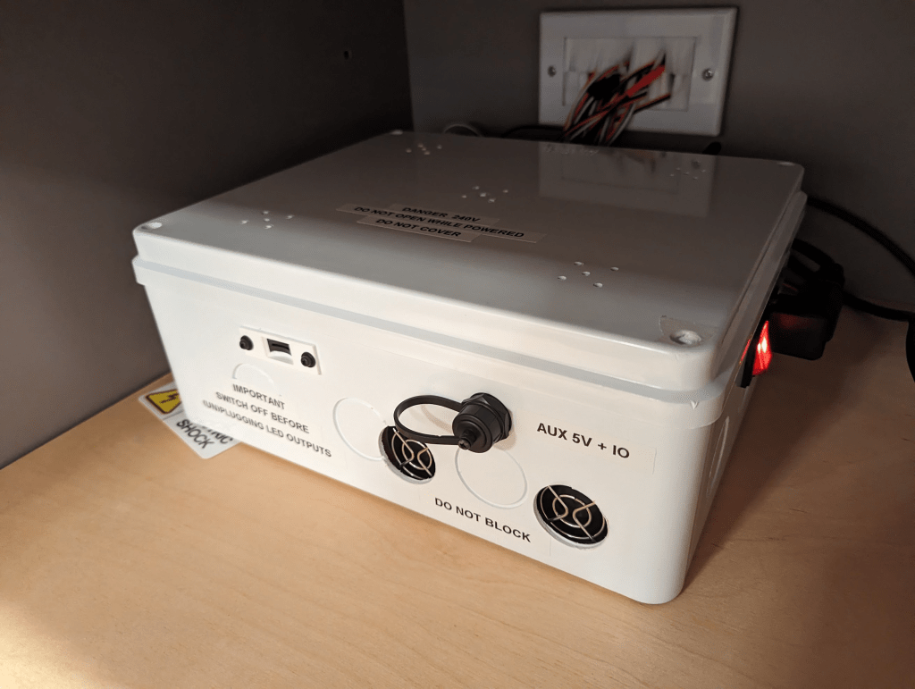
#whoops – A later inspection of the box revealed that it was getting quite warm inside, so I also added a few clusters of vent holes in the lid.
For safety, I used non-conductive nylon stand-offs to screw stuff to the case. I wanted to trade the strength of metal ones for the knowledge that if a wire came loose, those screws on the underside of the case couldn’t become live. Note you can see the metal fan housings of the power supply, but these are earthed (expected, but double-checked) inside the power supply somewhere. I’ve seen other projects use a mesh grid thing inside the box that’s easier to attach stuff to, but I couldn’t find one for a box this size.
Power
Choosing a power system took quite a while. There was one main factor to decide – voltage. The LEDs are 5v, and (with a bit of finger-in-the-air estimation) the longest strip will be 450 LEDs * 60mA = a draw of 27 amps! A problem with this, is that as amps and wire lengths increase, voltage drops (see voltage drop calculator). A drop in voltage too far below 5v will stop the LEDs from working, and possibly damage them – 27 amps with a 3 metre wire run just to get to the LEDs is going to drop that voltage down to 3.4v – way below where it needs to be. So working with 27 amps isn’t feasible as you’d need a wire as thick (and as expensive) as your arm to reduce voltage drop enough to be viable, and a thin wire would overheat anyway (🔥). Even if you could get a thick enough wire up from the control box, the copper wire embedded inside the strip and connecting all the LEDs together couldn’t accept that kind of current.
The solution is to reduce the current and increase voltage, then use a voltage converter nearer to the LEDs to swap it back, and inject more power mid-strip so that the strip doesn’t need to carry all of that current from one end to the other.
I decided to use 24v for the main wiring (the readily available choices are basically 5v, 12v or 24v), stepping back down to 5v closer the LEDs with a buck converter, and inject power approximately every metre. The converters were pretty simple – 24v 2A goes in, 5v 10A comes out.
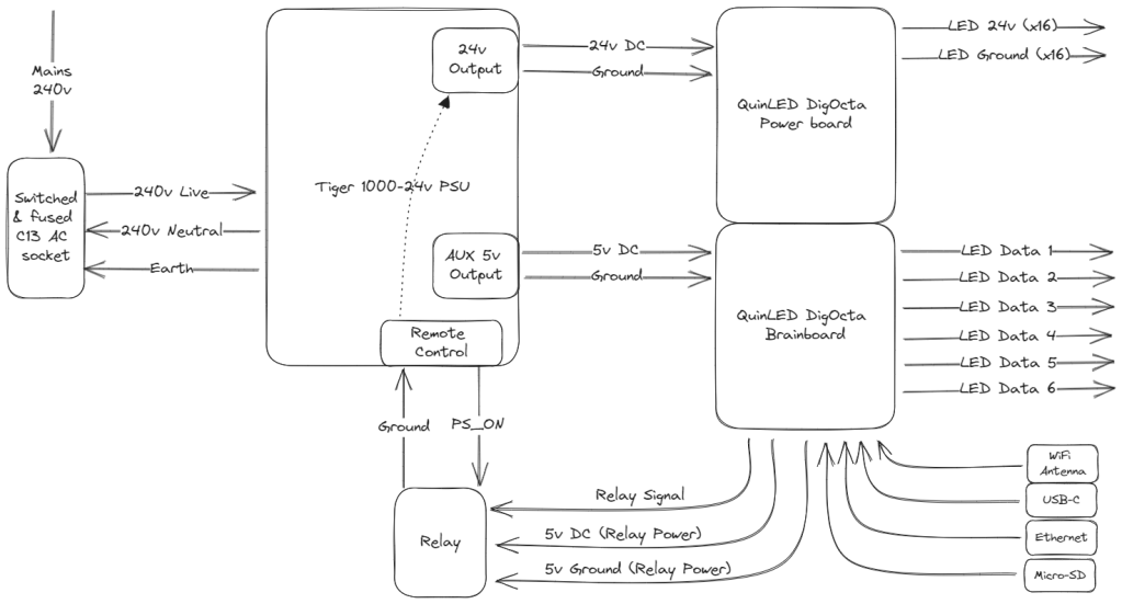
Overall, the 2500x 5v 60mA LEDs will need a minimum of 750W. I selected a Tiger 1000W-24v power supply – 1000W provides plenty of margin; you wouldn’t want to constantly run a power supply on its limits). An added bonus of this particular model is an extra 5v output that I can use to power the QuinLED controller, and a “remote control” feature that I can use to turn off the main power (leaving the 5v aux on) via the aforementioned power-saving relay – almost like it was designed for this project!
The relay I used was over-spec’d as I’d originally intended to use it directly on the 240v wiring, rather than in conjunction with the power supply’s remote control feature, but it was fine and did the job – it’s just a bit noisy as the contact closes when the lights switch on. I might revisit this in the future and swap it for a silent solid-state one, but while it’s not broken I’ll leave it alone!
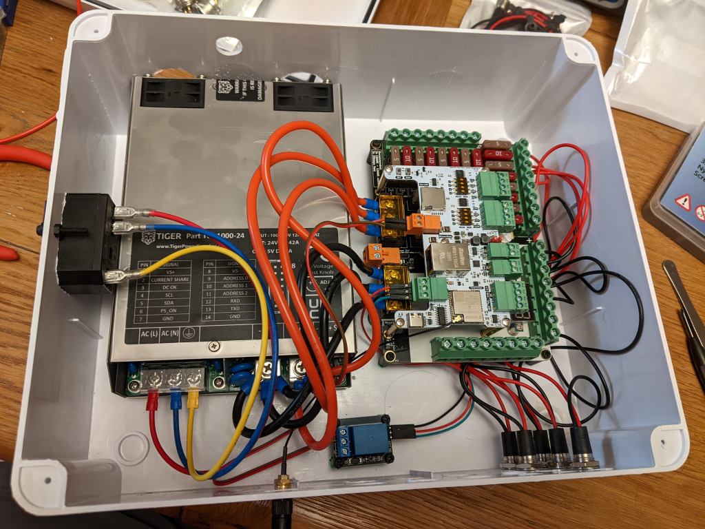
That leaves us with a schematic that looks a lot neater than the physical nest of wiring later turned out to be – see if you can match up the diagram with the photo! Omitted is the aforementioned earthing of the connectors – I joined these back to the mains earth with the grey lever block things.

Connectors
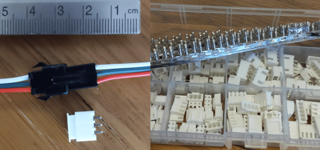
I chose these tiny JST XH connectors (white) to replace the big black ones that come with the LED strips, because they weren’t going to fit round the corners of the channels inside the unit. A small connector will be able to sit at the end of the strip without moving the last LED too far away from the end of the channel, though you can still see the black dead-spots in a few places.
I’m using these 3-pin DIN connectors for power+data outputs on the control box. They have a really solid feel, and also screw into their sockets to keep them secure. Working inside the 3-pin DIN plugs was fun – solder terminals hidden behind the metal casing, that weren’t as fiddly as I thought they’d be.

These run-of-the-mill DC barrel connectors were perfect for the power-only outputs, and as a bonus they come with a short length of wire already attached.
Testing
At every step I was testing every connection – after every solder, every crimp, and then overall as multiple parts came together. Most of these were continuity beep tests (a feature of the multi-meter) which just checks the wires are connected with a sufficiently low resistance. The rest of the testing was voltage – does everything actually produce 5/24v.
Where possible I did testing with the A/C feed unplugged – a 240v zap isn’t going to be pretty. But lots of tests require the outputs to be live. So when I was testing with A/C, for safety the box would always be shut with at least one screw in the lid and the screwdriver hidden under the power cord. Before the lid comes off, the power cord comes out and the switch off. I scared my wife a few times with “I’m turning this on – if it goes wrong, don’t touch me, pull the plug!”.
#whoops – A/C was connected so I could check the 3-pin and 2-pin socket outputs were correctly providing 24v. I accidentally shorted two parts of a DC socket together with my multi-meter probes, which caused a loud bang, a spark, and the power supply instantly revved its fans up to maximum. After deciding to open the box (with power off), I found that a fuse had blown (as designed!) and everything was otherwise intact, including the multi-meter. The power supply had taken the opportunity to rev its engines and dump all 42A through the short for a few milliseconds.
Buck Converters
The final piece of the core electrical work was building the 16 transformers that would sit close to the LED strips and step the voltage back down from 24v to 5v.
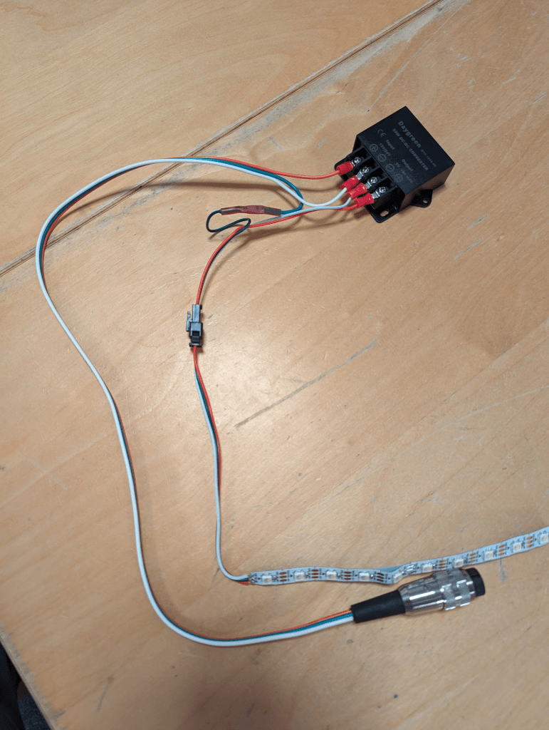
This is a power+data one that I created for testing. The 3-pin connector runs 24v to the transformer on its red and white wires, which steps it down back onto new white & red wires. The green data wire skips across the transformer and all three end up on the LED strip (soldered directly in this photo, which was a PITA). The green data wire has a pink heat-shrink solder joint on it where I joined two lengths of wire together – eventually I perfected the art of taking a length of 3-pin wire, prising apart the three cores at the right point, then cutting, stripping and crimping the red & white to join onto the converter, leaving the green untouched.
To be “ready”, each converter needed:
- A length of wire cutting – precisely measured by holding the reel up in front of the unit and going “about this much”.
- A control box connector attaching – either soldering on a 3-pin DIN plug, or heat-shrink solder-jointing a DC barrel jack, depending on whether it carried data or not.
- Crimped connectors for the four buck converter terminals, and screwing on.
- A JST XH connector crimping on to the strip end.
- Possibly steps 1, 2 and 3 again for the power injectors that serviced more than one segment of strip.
- Continuity testing, voltage testing
- Finally, a label – this was a small detail but saved a lot of head-scratching later as they got mixed up, crossed over etc, plus I got to use the label maker again! Numbered 1-6 for the strip #, and a letter A/B/C to identify converters on the same strip.
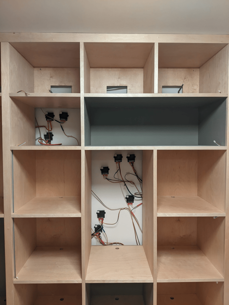
Some converters were straightforward (like the one above), others were a bit more complicated, where I had to continue the data connection from one strip segment to another at the same time as injecting power. All while Will was waiting for me (sorry Will!). I could’ve done some of this in advance, but without knowing wire lengths it was tricky. The result was that when Will was all finished, I’d have the transformers all screwed to the wall, and the little JST XH connectors popping out into each of the channels.
#whoops – At least a couple of wires had to be extended when I went to install them and realised there was a problem with my estimations.
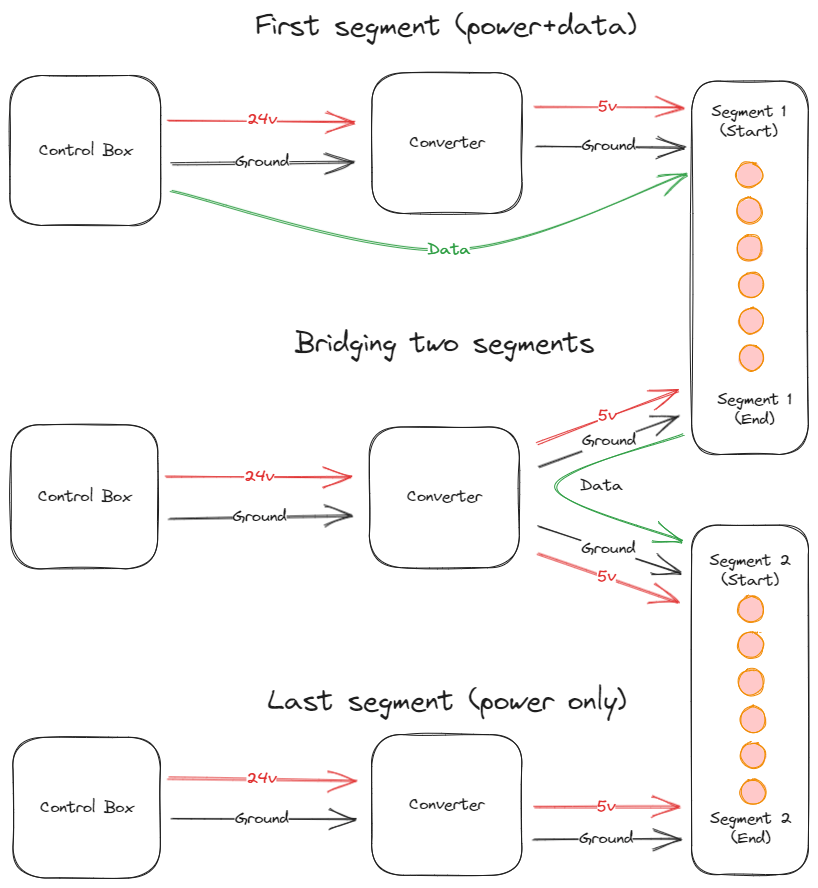
There were three main arrangements of buck converter to build, though some were more complex and had unique arrangements where they connect multiple segments together.
4B was especially unique as it sat between the two centre uprights, and had to be placed in the cupboard underneath, hidden inside its own little junction box to protect it, rather than screwed to the walls like the rest. This required some extra connectors and wiring faff, harder testing and resulted in a random box floating around in the cupboard. In hindsight I could’ve put this one inside the main control box to tidy it up – it would be a useful technique for the next big Games Room project.
#whoops – A couple of the JST XH connectors turned out to be loose and pulled off after wiring was installed in the unit. These were a nightmare to re-do in the tiny confines of the shelving. In some places the auto-strippers and JST crimps were just too big, and the wires too stuck (either too short or accidentally trapped in the wood structure) to do it sensibly, and I ended up redoing them very carefully with a pair of pliers and considerable patience – “if I get this wrong I won’t have another chance to fix this now that the unit’s glued together” – kind-of-patience.
#whoops – At one point I dropped two terminal screws and a wire down the back of the unit after it became uncrimped from its terminal on the buck converter. After many attempts I was able to use a magnetic telescoping stick thing to retrieve them. After that I used cable clips to secure all the loose wires to the wall a bit better.
Stripping
After the flurry of work racing against Will, I was able to sit back and put the LED strips in at my own pace, which ended up taking a couple of weeks doing a bit at a time depending how I was feeling – some days were harder than others, especially when problems turned up with it.
#whoops – I neglected to test the wiring once they were in-place, but before Will had glued the unit together. One particular wire was completely dead, but fortunately it was in a unique position where I could instead bridge two strips together directly. I got lucky.
One at a time, I would cut a strip down to size or solder it together with others to make the right length. Then solder JST XH sockets onto each end. A trick I found was to add a (wired-up) plug in the JST XH socket to keep the pins aligned, as the soldering iron’s proximity tends to melt the casing a bit. Then test the strip and start pushing it into the channel, while slowly peeling off its sticky back.
#whoops – more than once I forgot to make sure the sockets were the right way and had to remake/resolder them /facepalm
#whoops – The strip was quite hard to get into the channel sometimes, I used the tip of a pair of pliers to gently push it in. Once I did this while the strip was live and caused a temporary short. Fortunately I didn’t kill the strip.
#whoops – A couple of times I used too much force with the pliers or fingers and break a solder joint in the strip. I managed to resolder these in-situ thanks to the SolderM8, which makes joining strips much easier by holding them in-place. Removing the strip would’ve meant ruining the sticky back.
The couple of 90 degree corners were fun – I had to bridge two strips together with bits of wire, protected by hot glue and will-power. Tricky and fragile, but they look ace when the diffuser’s on.
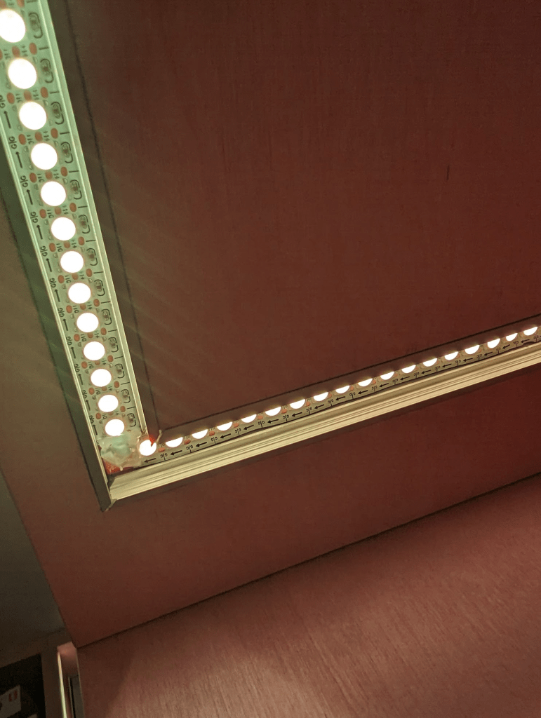
I would then measure and cut the diffuser with a pair of aviation snips that Will recommended. It’s quite satisfying pressing the diffuser into the profile – it makes a cool noise as you sweep your finger along to click it in. I cut the couple of 45 degree corners by eye – I should’ve measured them really as it took a few goes.
Automation
The final step after it was all assembled, tested, and effects chosen, was automation. I used WLED’s built-in preset/playlist functionality to create the startup effect, and have it transition in to the main show. I used Home Assistant’s WLED Integration to tie together a presence sensor and a door sensor to automatically “lights on” and “lights off” when someone walks in or leaves – this adds a touch of magic that makes it feel even more sci-fi.
#future-whoops – Add a “sleep” mode for when someone’s crashing overnight in here!
In the end
This was a fun project that occupied a large part of my mind for a few months, and is only the beginning of my LED work in the Games Room, though by far the most complex bit of my journey. There’s been a lot of #whoops along the way – all lessons learned for next time.
I need to thank Will for his patience not just during construction, but also all the design work beforehand and embracing the idea in the first place – we love the work he’s done for us (here and elsewhere in the house), and it’s not the last we’ve seen of him. I also need to thank my lovely wife for her patience, embracing the insanity, and only complaining a little bit about the soldering smells. I also want to thank the other friends & family that I bounced ideas off and the little tips that came in from them. And finally, thanks to every person that steps in the room and exclaims “omg this is amazing!!1!”.
Part 3 covers my workstation that follows a similar design.
Ingredients
For anyone that’s foolish enough to want to try their own, these are the ingredients I needed to make it possible.
Resources
- QuinLED’s general articles about LEDs [Link]
- Voltage drop calculator [Link]
- WLED docs [Link]
- How To Crimp JST XH connectors [Link] (Bonus points for being exceptionally quick and concise!)
LEDs
- BTF-Lighting’s SK6812 RGBW Natural White LED Strips, 144 pixels/metre [Link]
- 3-pin 18AWG wire [Link]
- PH2 Aluminium LED Profile, with Opal diffuser [Link]
- DC Converter 24v -> 5v [Link]
- JST XH connectors [Link]
- Cable clips [Link]
Control Box
- QuinLED DigOcta Brainboard [Link]
- QuinLED DigOcta Power-7 [Link]
- Tiger TGR1000-24 Power Supply [Link]
- AC switch [Link]
- 5v Relay [Link]
- Junction Box [Link]
- Panel mount ethernet extension [Link]
- Panel mount USB-C extension [Link]
- MicroSD extension [Link]
- MicroSD extension panel mount adapter (3D print by MichaelOlson) [Link]
- 3-pin connectors [Plug][Socket][Shield Ring]
- DC barrel connectors [Plug][Socket]
- Quality C13 kettle lead
- Heat shrink [Link]
- Nylon stand-offs [Link]
- Connector blocks [Link]
- Red/black 16AWG wire [Link]
Tools
- Soldering iron [Link]
- Soldering Mat [Link]
- Multi-meter [Link]
- Crimps/auto-strippers [Link]
- JST XH crimp [Link]
- Ring crimps [Link]
- Heat gun [Link]
- Heat shrink butt splices [Link]
- Helping hands [Link][Link] (to be honest neither of these were amazing, but something like it is crucial)
- Solder M8 [Link]
- Hot glue gun [Link]
- Aviation snips [Link]
- Step drill bits [Link]
- Electrician’s rods (invaluable for feeding wires around the back of the unit) [Link]
Ed

Leave a comment