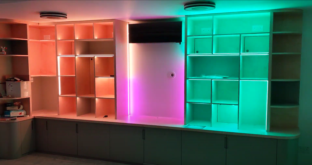
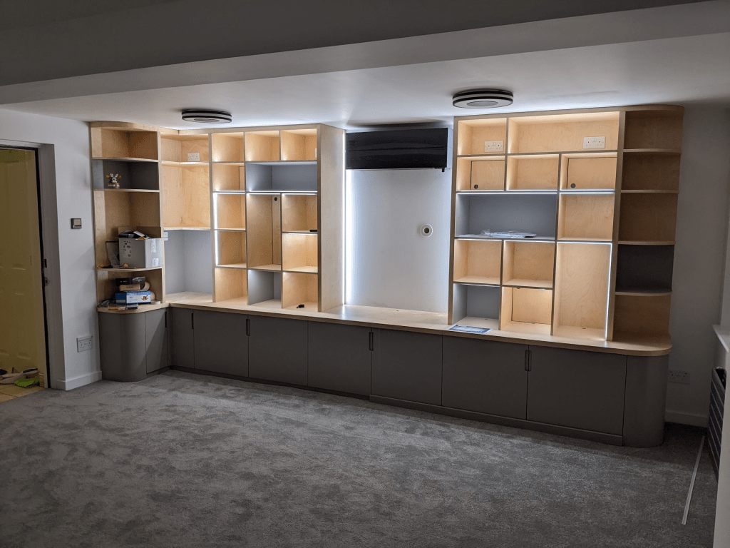
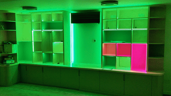
For our newly-built Games Room, we wanted a nice place to store and display our board game collection, and general geekware (mostly Lego). As it would be a dominant object in the room, we wanted it to contribute to the general lighting, as well as turning its contents into a showpiece.
I’m writing this post partly by request, partly for my own recollection in the future, but also because I like sharing about the things I’m doing (as my colleagues are quite aware – a few of them will know most of this story)! Roughly speaking this part is the “what”, and part 2 is the “how”. This jumps around a bit out of chronological order so that the shiny stuff is first (after this initial bit of explanation…)
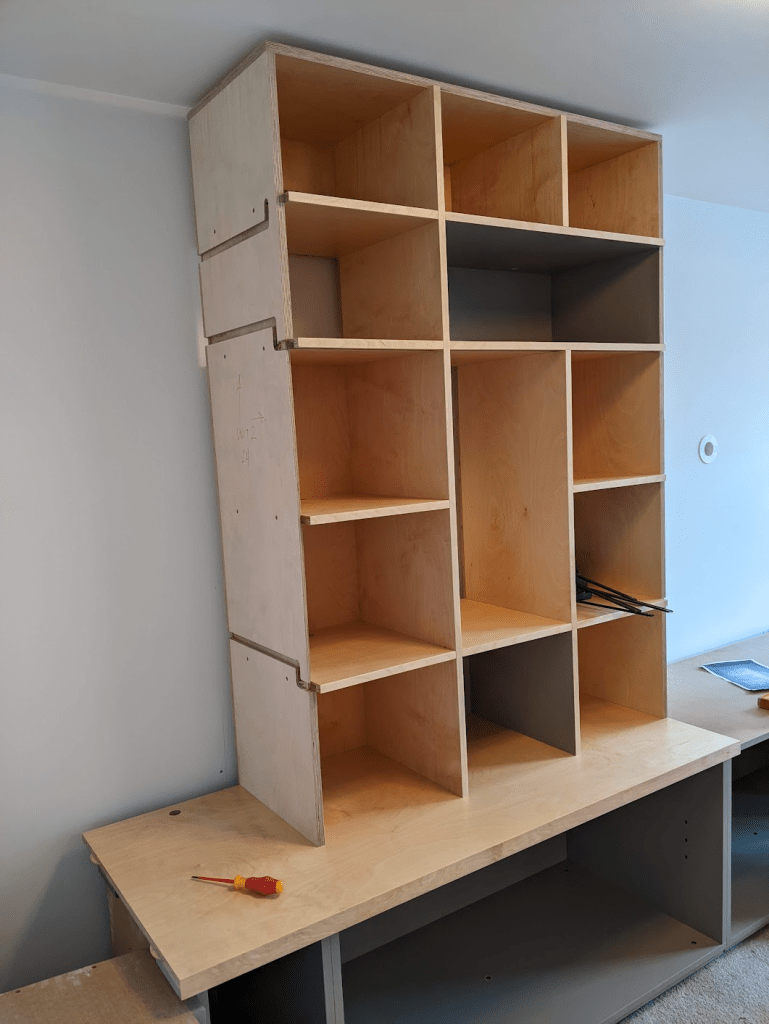
While I have some basic electronics knowledge (though far less than would be needed for this project), I have little experience with furniture making. With a colleague’s recommendation, we had a carpenter, Will – WJS Creative Furniture, who was on-board with my crazy ideas and brought a lot of his own too. He’d handle the making-stuff-from-trees bit of the project, and I’ll do the electronics. From there, I started researching…
I could’ve accomplished a lit storage unit with off-the-shelf LED systems – just bits of strip you plug together, plug into a driver and done. But there were a few things I wanted, that when combined made this complicated and meant I wasn’t just going to be able to simply buy the features I wanted:
RGBW – RGB (Red Green Blue) lights because they look awesome, and W(hite) because I do want the room to be able to have a more “normal” look, eg when using it as a home office. RGB can produce white on its own, but it’s not a particularly pleasant white with gaps left in the spectrum that make it look a bit odd in comparison to a regular white light bulb. RGBW strips are slightly higher cost, and need slightly more power to run.
Control – I’m a software engineer and smart home fanatic – I wanted programmable control over the lights. This meant I couldn’t just plug them into a commodity RGB LED driver and use one of those “colour” remotes that you get with cheap consumer RGB light bulbs and lamps. I wanted to be able to change the lights automatically, eg based on time of day (night light with less blue in it), brightness (a bit dimmer in the evening), or in response to something dynamic, like themeing it to the current player who’s King of Tokyo on Game Night [see – future project!]. This means a proper microcontroller, networking, Home Assistant integration are all important.
Individually Addressable – Basic RGB strips have a single input for colour that is taken on by all LEDs in the strip. I wanted to be able to program each LED individually. This enables cool effects, animations, being able to change the colour of individual shelves – perhaps Lego Bowser would look best bathed in red, and the board games in a simple white. Some addressable strips are a hybrid and have their LEDs in groups that show the same colour together – typically in threes. While it has simpler voltage requirements, this wouldn’t have produced the effect I wanted, creating wider blocks of colour rather than points.
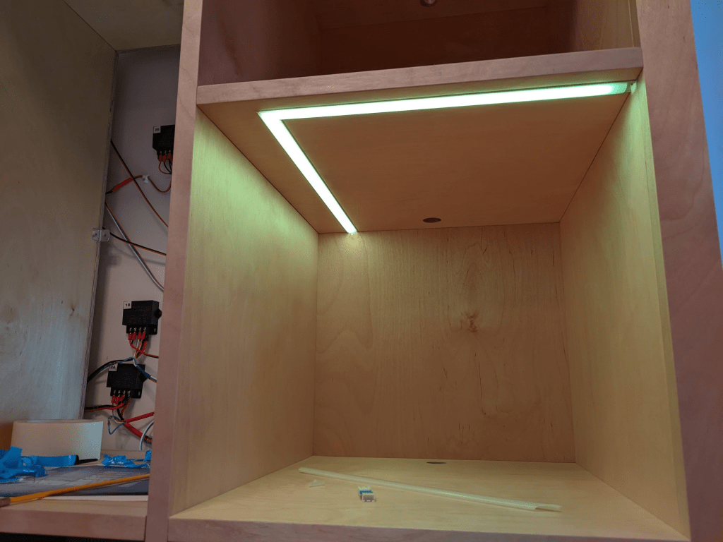
Spotting – LED strips come with varying numbers of LEDs per metre. More LEDs means you gain a higher resolution for effects, and a smoother appearance that reduces spotting. However there are a few downsides; higher cost, higher power requirements, higher thermals, all of which make them more difficult to use. I really dislike the look of a spotty LED strip – you see these all the time once you become aware – a bright strip of LEDs running down a wall with a hotspot over each one. A higher density strip reduces this effect by allowing you to run each individual LED dimmer, and blending their outputs together. For me, the upsides of a higher density strip outweigh the downsides. Spotting is also significantly affected by the depth of the LED channel and the type of diffuser you have on it.
Experimenting
I did some experiments with different strips, profiles and diffusers before settling on one.
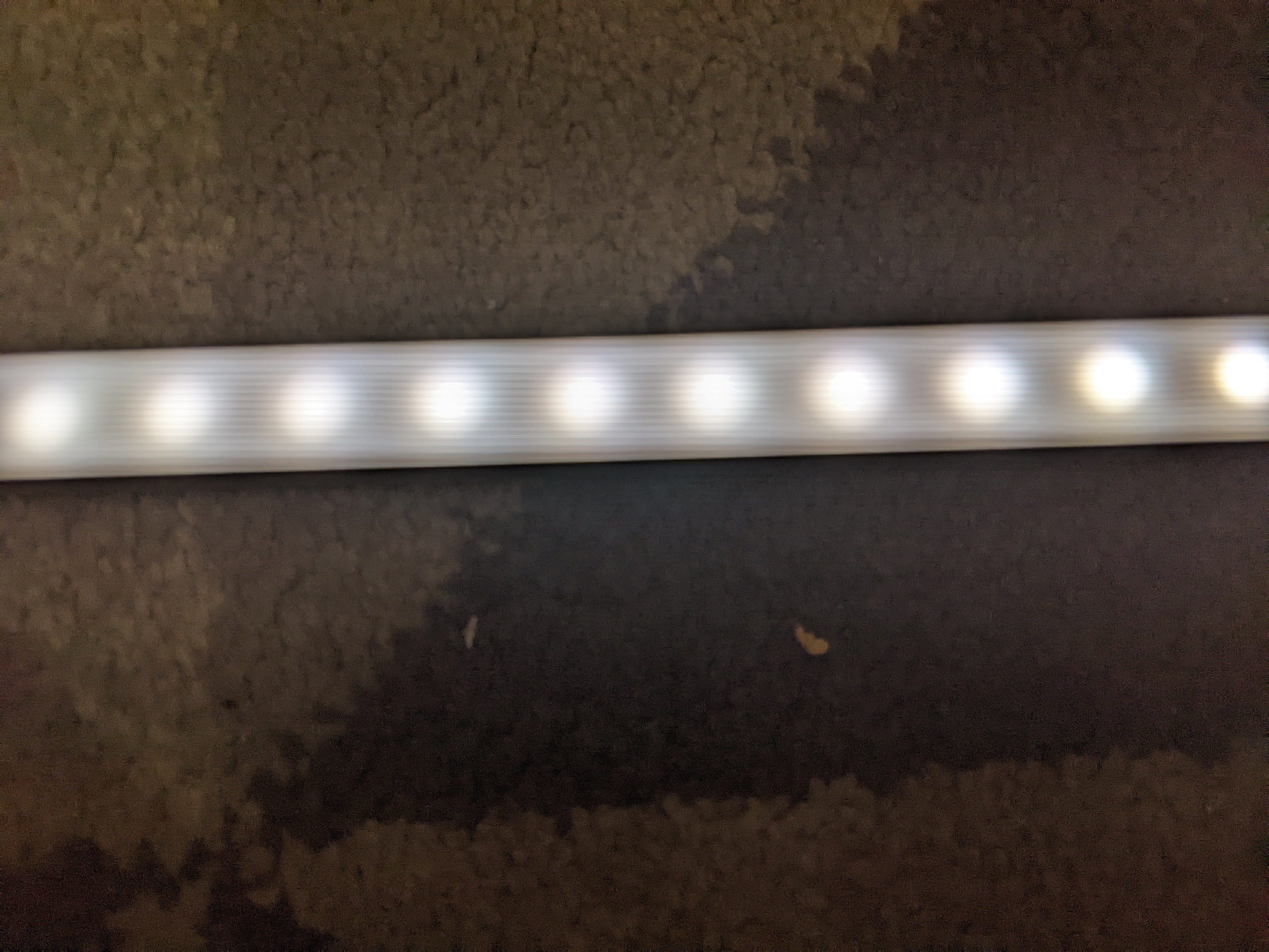
60 LEDs/metre – too spotty
144 LEDs/m – still too spotty
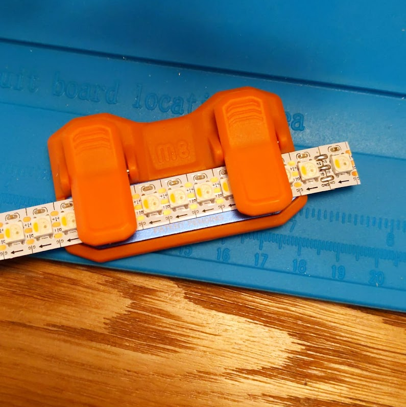
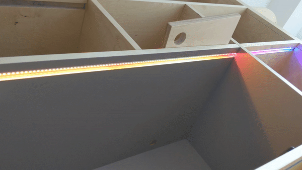
144 LEDs/m with a deeper aluminium channel – perfect!
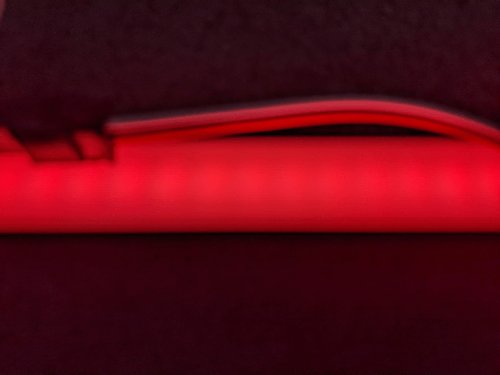
Mocking up a shelf with the strip facing downwards, inset from the front edge to check brightness, and how visible animations are when seen indirectly.
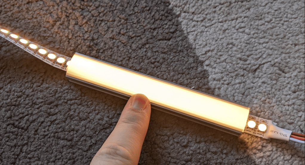
It took me a while to find a channel that did the job. I knew I needed a deep channel to avoid spotting, but the standard depth for “deep” is 16+ mm. The shelves are 18mm thick, which after routing would leave only 2mm – Will was concerned this would make the shelves weak. Eventually I found MarcLED sell a bunch of profiles that I’ve not seen elsewhere, so I ordered some samples and their 13mm PH2 one (above) did the trick. It also had a nice little bonus that I didn’t discover until the very end of the project – because the diffuser is slightly domed you can see the light strip when looking at the shelf from the side and looks really cool. This does create a little bump above the shelf surface, but the contents weren’t going to cover up the strip anyway!
Layout
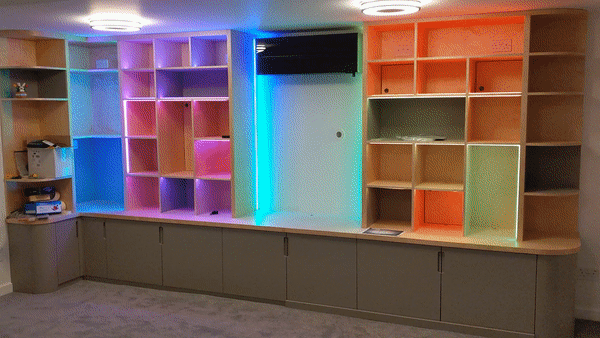
An exciting part was choosing how to lay out the strips. This brings questions like… which cubbies are lit, which side of the cubbies do the strips go on, do they go at the front of the cubby or the back, how do I get the wiring from the back of the unit to the strips? After a few iterations with Will, I landed on this lighting design.
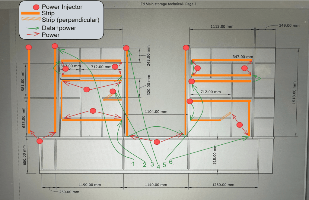
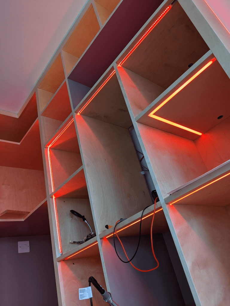
I’ve created six continuous runs of strips, each 2-3m long, that go through the wood from cubby to cubby. Will used this plan to route channels inside the structure to get wiring from the front to the back. I’ve made sure that every shelf has at least some lighting in it.
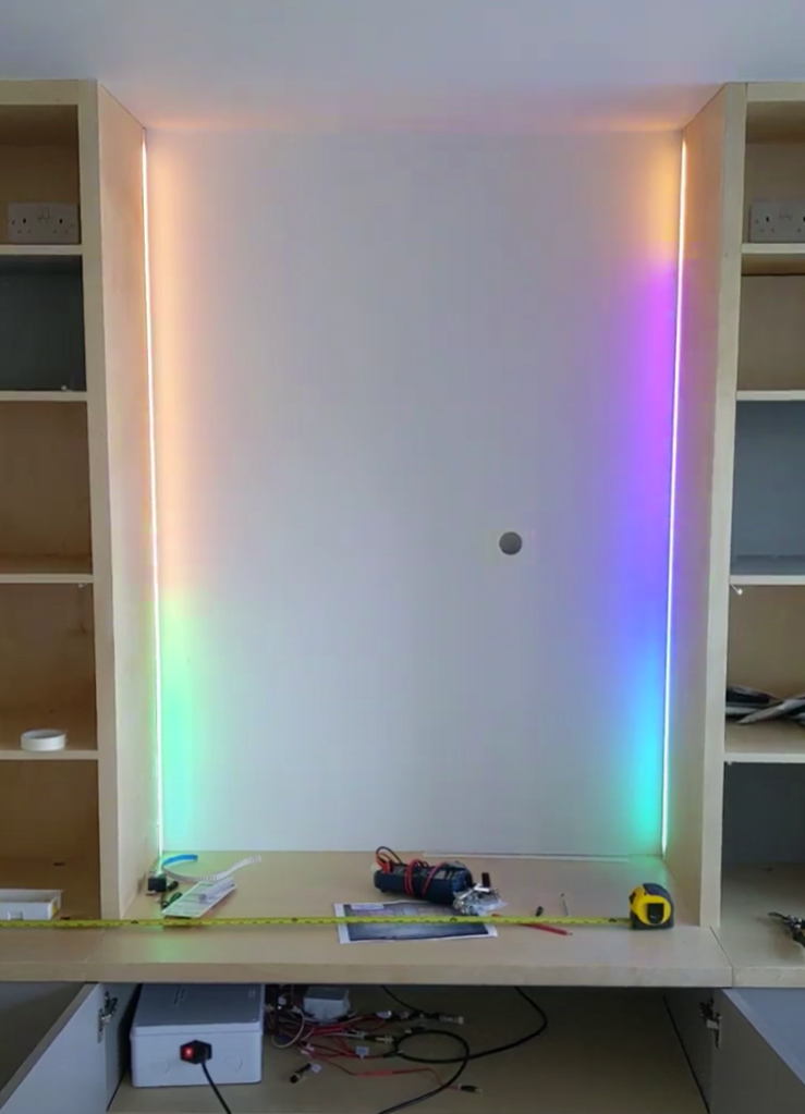
The horizontal strips below eye-line are facing down, and those above are facing up. This reduces the apparent intensity of the strips when using the room – I thought it wouldn’t be pleasant to be seeing them all directly, with just a few vertical ones that you do see regularly. This negates some of the point of the spottiness testing that I did, but you do still see them sometimes.
I divided the unit into four main sections – the corner and centre have two simple vertical strips to side-light the columns, and the centre one is set back to create a wall-wash behind the TV that will go in the big space.
The other four runs are in the two systems of cubbies, with two on each side. For flavour (and wiring simplicity), some of the cubbies are lit vertically, and two feature a 90-degree corner that goes to the back of the unit.
#whoops – There were a couple of things that didn’t go to plan – notably at the Big Switch On. Just as the show started, FPP crashed and I had to turn everything off and on again, making sure to bring stuff back up in the right order while stood on the drive with an audience of family & friends – no pressure! I later filled a bug, and the FPP authors had got it fixed by the next day.
Will used the layout plan to add wiring channels from the strips to the back of the unit. Hiding them inside the structure of it, I would have to install wiring as he was putting it all together. He made a tweak to these before I started actually laying wires, so that the angles in the routing were 45 degrees rather than 90 to help the wires slide smoothly back & forth after installation.
While Will was working (*some of which was spent waiting for me to catch up – sorry Will!), I constructed and installed all of the wiring. I hadn’t been able to do this in advance because I didn’t want to accidentally make wires too short (and have to extend them), or make them way too long and introduce voltage drop (and waste wire). Holding off until the physical unit was present was a good thing, as my estimates had been too short, and I ended up having to order more wire to be ready for Will’s second day.
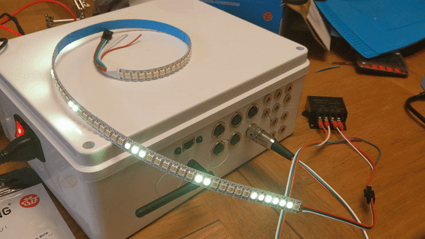
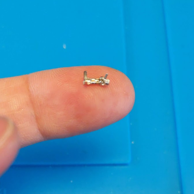
The things that took me the longest while Will was here, was soldering the big 3-pin connectors onto each main wire, and crimping the teeny-weeny JST XH connectors on the other end – I reckon I did about 30 of these, and now I’m really quick at them – each connector has three pins, and each pin has two crimps on it. Quite a few went wrong early on, but by the end I was cranking them out.
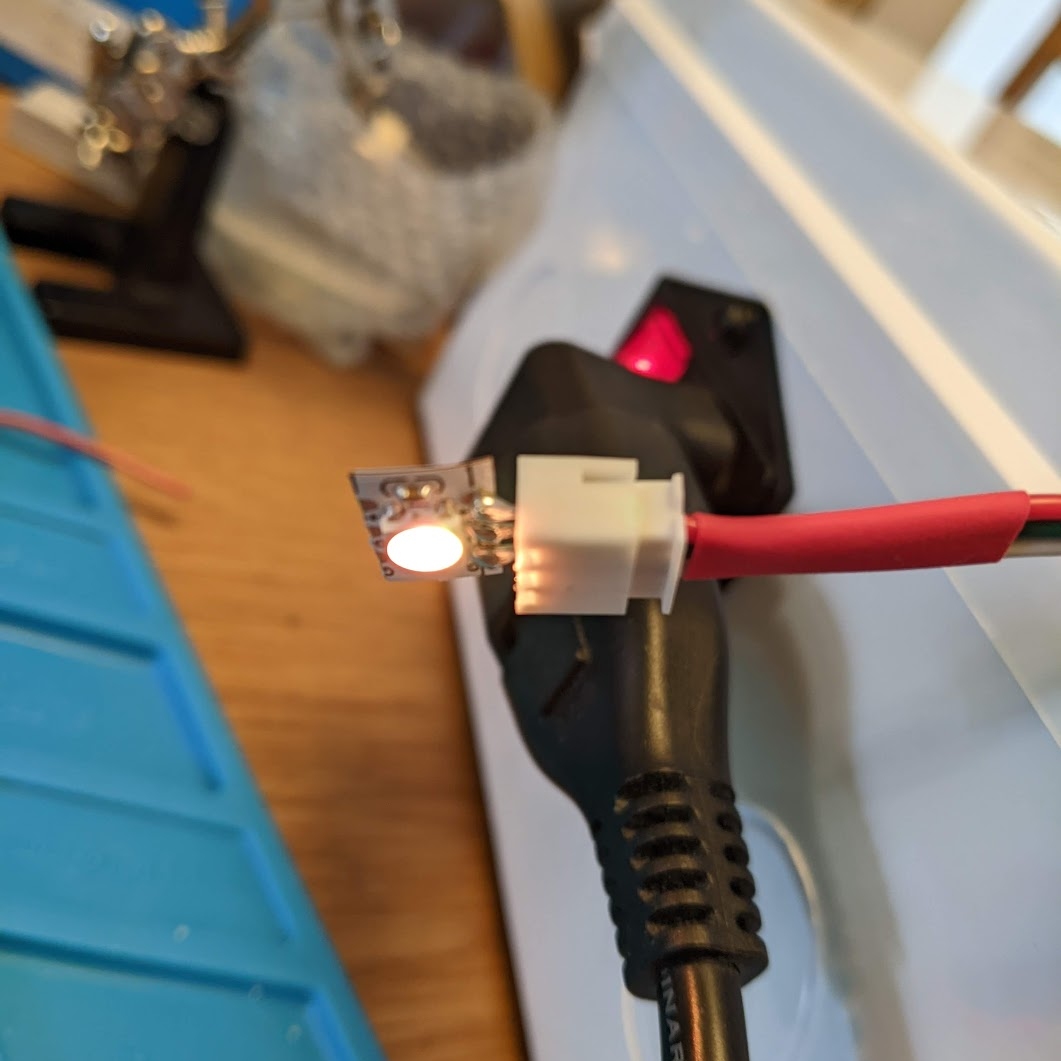
When Will was finished, the wiring was in-place, and he’d cut & glued all of the aluminium profiles. “All” that was left was for me to install 16m of strips, which involved cutting them to size (or soldering leftover bits of strips together to make new sections), soldering teeny-weeny JST XH sockets on the ends of them to connect to the wiring, stick them in, and cut the diffusers to size.
Effects
Skipping ahead to the after everything was done, I had to use summon some artistic skills to actually make what I’d built look awesome, but first I had to have a play – the software I chose (spoiler: WLED) has 100+ effects to choose from, and a load of preset colour palettes (as well as custom ones). Sadly I don’t have many videos from testing, but here’s a quick sample…
For the real thing, I wanted two main effects – a “turn on” that looks awesome, and a continuous effect while the room is in use. No “turn off” effect, because no-one would see it as the room’s lights are controlled by a sensor – empty room for 30s = lights off!
Eventually I settled on sweeping lights that eventually all turn on, and then switch to a red/yellow washing machine that periodically spins back and forth, which plays until they’re turned off. I still need to work on the transition a bit as it’s quite jarring, but I’m happy with the main sections. This gif is unapologetically long…
That’s all for now; thanks for reading if you got this far! In part 2, I talk about the technical aspects of the electronics and the control box, which felt like more than half the job on its own!
Ed

Leave a comment